When my wife and I bought a house a couple years back, I knew it would only be a matter of time before I started getting into home automation. My house, like many built in the late 90s, was pre-wired for an alarm system. While I had no desire to revive a 20-year-old alarm panel, it did mean all my exterior doors were pre-wired with inconspicuous sensors. I already run Home Assistant on a Raspberry Pi, so I was looking for a way to integrate these hard-wired door sensors with what I already have. I had read about these cheap WiFi-enabled ESP8266 boards, so I decided this would be a simple project to try it out with.
Breaking into the existing alarm system
The brains of my old alarm system were tucked away in a wall-mounted cabinet in my laundry room.
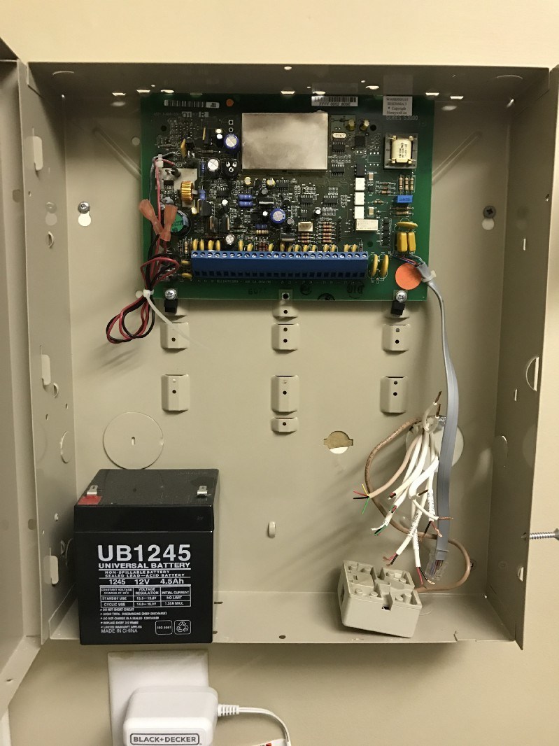
All the sensor wires were cut back, meaning I had to strip each one and trace what they did. It was decently quick work with my multimeter and a wife to open/close doors for me. Since the existing sensors were just simple reed switches, the two wires from each door would short when the door was closed, and open when the door opened. I guessed correctly that the small 2-conductor wires went to my three exterior doors, but honestly, I’m still not sure where the rest of them go.
Making it work on a breadboard
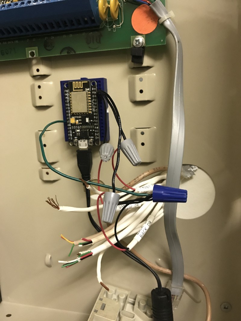
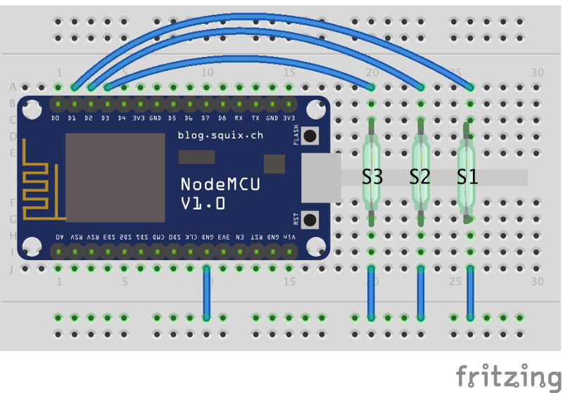
Now the fun part: building it. This is a super simple circuit, with just a microcontroller and 3 switches. I used 3 of the GPIO pins to connect to the 3 door switches and connected the other side of the switches to ground. One nice feature of this board was that most of the pins had a built-in weak pull-up resistor. This meant that when a switch was open, the pin would be pulled high (3.3V).
Adding some code
All of my source code is on GitHub, so feel free to check out that repo and see how it works there. This is my first time using Lua, so I’m sure there are things that can be optimized in this code. Feel free to submit an issue or PR if you find anything that stands out!
- init.lua: the simple startup script. Best practice is to keep this file relatively simple and give yourself an opportunity to break out of the boot cycle should your app have an issue.
- secrets.lua: secret variables such as WiFi credentials
- config.lua: just some simple configuration variables
- sensor.lua: the brains of the project. All of the real logic lives in this file.
I won’t get too detailed here, but after establishing the initial WiFi and MQTT connections, the application code is triggered asynchronously by an interrupt when a change on one of the door sensors is detected.
Preparing the NodeMCU board
Before I could run my code on the NodeMCU board, I needed to flash it with updated firmware that contained the modules I needed. I used this handy Cloud Build Service to build a firmware image. For my needs, I simply needed the following modules: file, gpio, mqtt, net, node, tmr, uart, wifi.
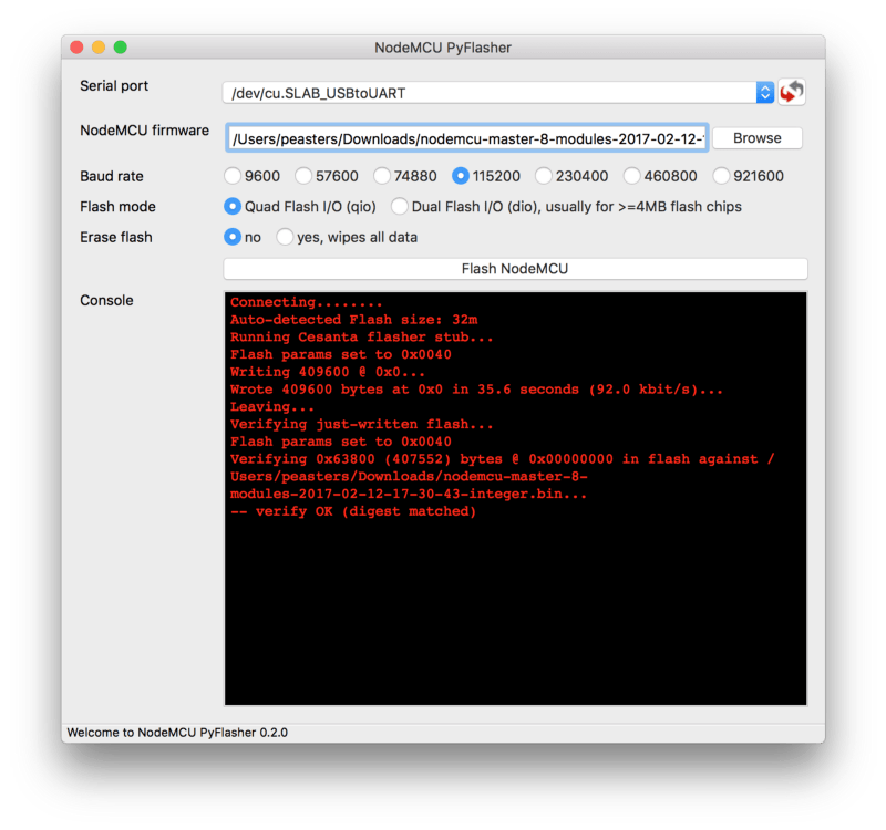
To actually flash the firmware, I used an open-source Python tool called nodemcu-pyflasher. It worked great on my Mac and should on most other platforms as well.
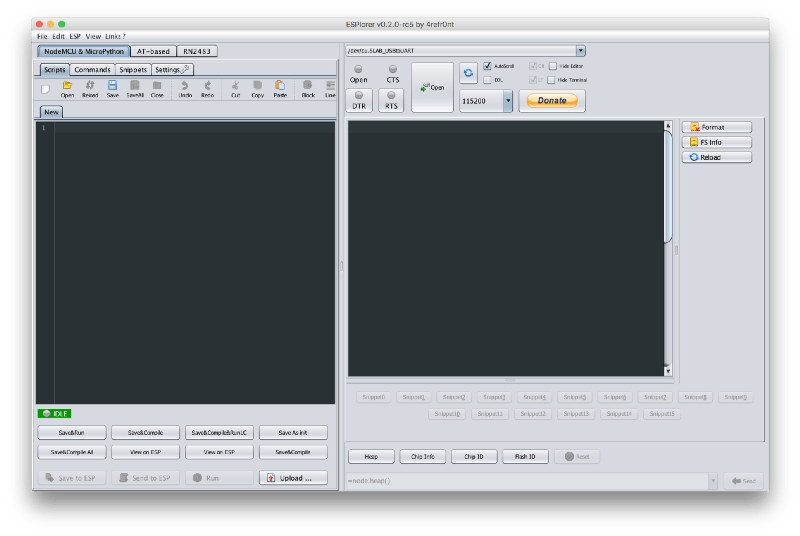
Now that I was ready to upload my code, I used a tool called ESPlorer to handle that portion. It provides a pretty handy console that lets you run commands ad-hoc as well as edit your code. I personally found it easiest to just use my usual text editor and the “Upload” button in the left pane.
Integrating with Home Assistant
Like I mentioned before, my home automation platform of choice is an open-source app called Home Assistant. It has a strong community backing and the maintainers are constantly pushing new releases. While I could have used the built-in REST API, I opted to use the MQTT protocol for a couple of reasons: first, MQTT is super lightweight and perfect for the modest compute resources of the NodeMCU board; and second, it’s a more universal protocol that can be used outside of the Home Assistant ecosystem without changes. If you use Home Assistant, I configured my door sensors as binary_sensors. The snippet for one sensor is below, but you can look at the rest of them in the Github repo for my config.
- platform: mqtt
  state_topic: "pat/alarm/Front Door"
  name: "Front Door"
  payload_on: "open"
  payload_off: "closed"
  device_class: opening
Wrapping it up
Thanks for reading this far! Hopefully this project inspired you to build something of your own or saved you a bit of time as you tackle something similar. I’m happy to clarify anything or answer questions, so feel free to reach out here or on GitHub.
Resources
NodeMCU Documentation (super thorough and helpful) Project Code Home Assistant Config